circuit 1A examples
Circuit 1A - with full block controls - is built into some, but not all, of the Thompson double line block instruments.
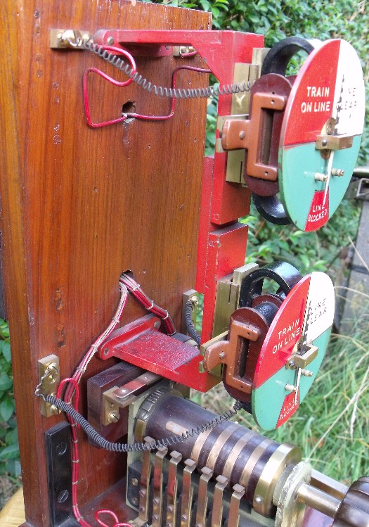
The reduced version with only signal proving (home normal control) is referred to under early circuits. Example 1: Here's a fine example of a Thompson double line block instrument. Originally it had a bell tapper - indicated by the brass 'mouse-hole' at the bottom right - but this was removed at some time.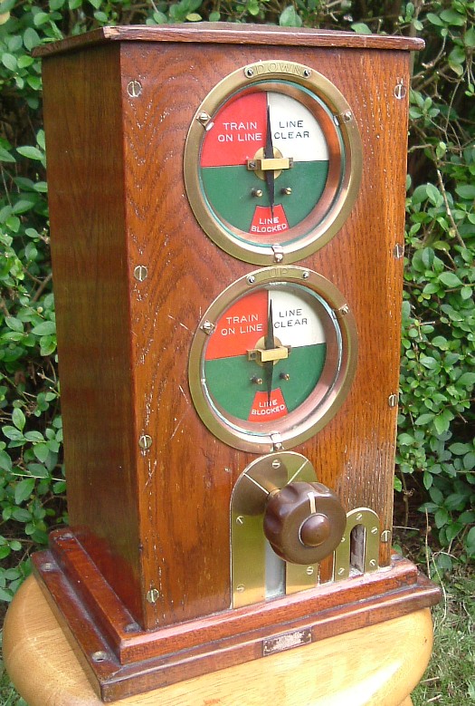 Looking inside, we can clearly see the LCS (Welwyn control) and BCS (signal proving) relays.
The ratchet contact for dropping LCS is partly obscured by the lower (pegging) dial.
Looking inside, we can clearly see the LCS (Welwyn control) and BCS (signal proving) relays.
The ratchet contact for dropping LCS is partly obscured by the lower (pegging) dial.
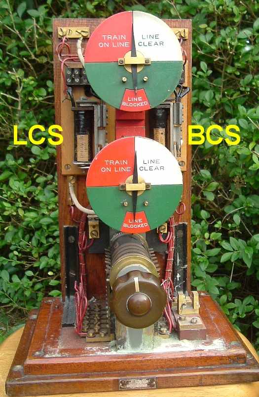 Interestingly, the coiled wires to the needle units (dials) have been stretched and the connections reversed; if done
by the railway, this may indicate the block was used in a 'negative line clear' area.
The brass work has been well polished, if the deposit of dried brasso is anything to go by!
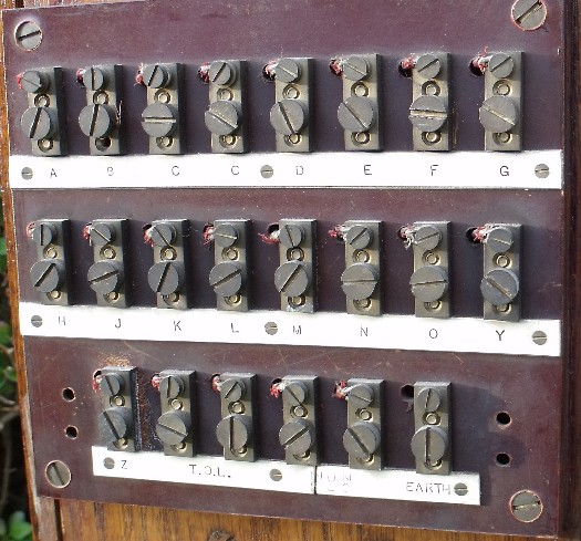
On the back of the Thompson blocks, there is a neat array of screw terminals:
Interestingly, the coiled wires to the needle units (dials) have been stretched and the connections reversed; if done
by the railway, this may indicate the block was used in a 'negative line clear' area.
The brass work has been well polished, if the deposit of dried brasso is anything to go by!
On the back of the Thompson blocks, there is a neat array of screw terminals:
 Example 2:
This Thompson instrument has a plunger instead of tapper:
Example 2:
This Thompson instrument has a plunger instead of tapper:
 Here's the back of the instrument, showing the plunger contact mechanism.
 Circuit 1A uses a ratchet-contact to drop the LCS (Welwyn) relay. These contacts are
indicated in this interior view:
Circuit 1A uses a ratchet-contact to drop the LCS (Welwyn) relay. These contacts are
indicated in this interior view:
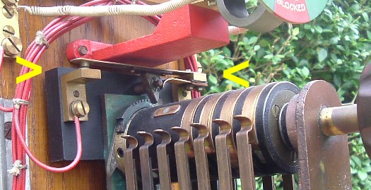 In this picture, the commutator is in the central line blocked position.
Moving the commutator anti-clockwise from line clear back to line
blocked raises the bar (between the arrows), breaking the
contacts at the left.
Example 3:
This Thompson instrument is unusual.
In this picture, the commutator is in the central line blocked position.
Moving the commutator anti-clockwise from line clear back to line
blocked raises the bar (between the arrows), breaking the
contacts at the left.
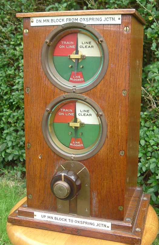
Example 3:
This Thompson instrument is unusual.
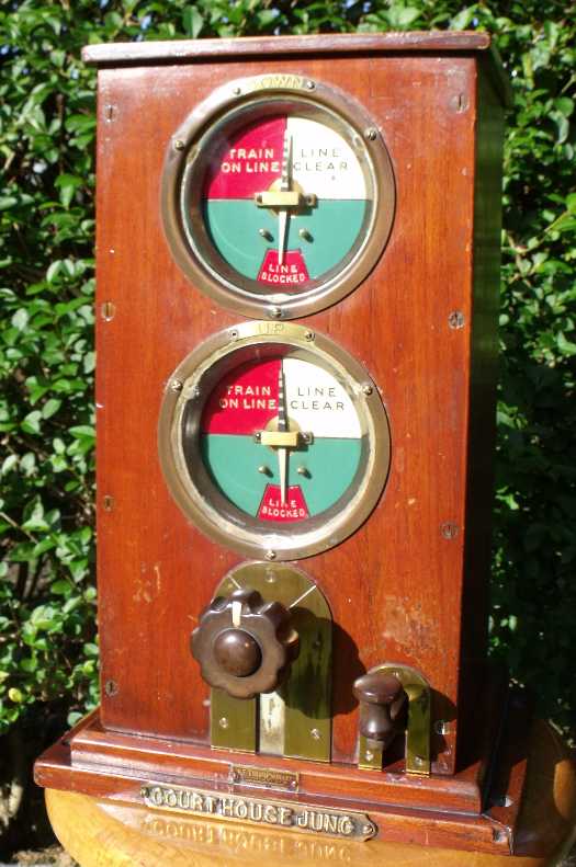 The LYR-style cast brass plate along with the UP and DOWN designations indicate it came from Barnsley Exchange Junction. It has a test
label dated 31-12-1953.
The LYR-style cast brass plate along with the UP and DOWN designations indicate it came from Barnsley Exchange Junction. It has a test
label dated 31-12-1953.The surprise comes on looking inside. It has the ratchet contact - as required for circuit 1A - but there are no relays! You can see filled in holes where the relays may have been originally attached.
 Why someone would take a - presumably expensive - instrument and remove functionality from it, I
don't know. The ratchet contact is not now connected to anything (maybe it was too difficult
to remove!). The fact the holes are filled in, indicates the modification and re-wiring was
a careful, professional, job. The commutator itself is the same as in the other Thompsons.
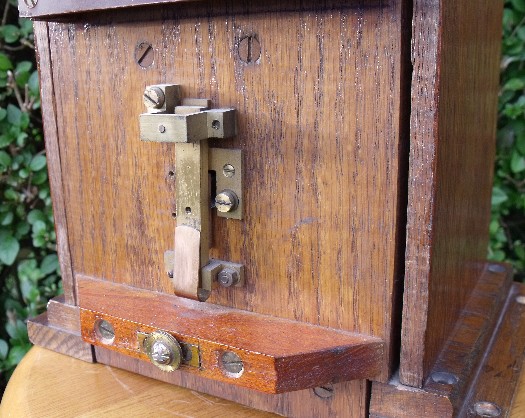
Looking on the back, we see it had a bell plunger at one time, and the terminal block is
different to the other Thompsons. In fact, all Thompson instruments I have seen (6 out of 6, so far)
either have a bell plunger, or have holes where a plunger was once fitted.
Why someone would take a - presumably expensive - instrument and remove functionality from it, I
don't know. The ratchet contact is not now connected to anything (maybe it was too difficult
to remove!). The fact the holes are filled in, indicates the modification and re-wiring was
a careful, professional, job. The commutator itself is the same as in the other Thompsons.
Looking on the back, we see it had a bell plunger at one time, and the terminal block is
different to the other Thompsons. In fact, all Thompson instruments I have seen (6 out of 6, so far)
either have a bell plunger, or have holes where a plunger was once fitted.
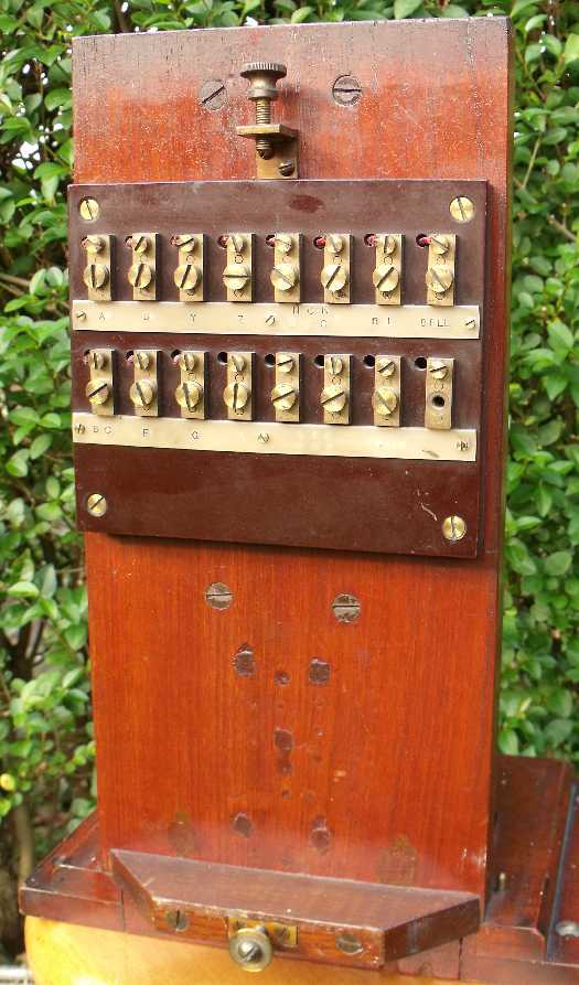 Here's the terminal block in more detail.
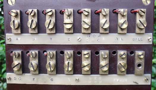 It is not clear if this instrument was used with block controls. There is no direct connection between
the commutator (terminal A) and the needle (terminals F and G), suggesting some form of control. On the
other hand, the terminals H and J are missing - these close at train on line or
line blocked, and are usually used to pick
up the track circuit stick relay after the track circuit has cleared.
It is not clear if this instrument was used with block controls. There is no direct connection between
the commutator (terminal A) and the needle (terminals F and G), suggesting some form of control. On the
other hand, the terminals H and J are missing - these close at train on line or
line blocked, and are usually used to pick
up the track circuit stick relay after the track circuit has cleared.