LNER and BR(ER) block instruments
The information presented here is based partly on an old book of BR(ER) 'Standard Wiring Diagrams', which I bought at auction a few years ago, and partly on my observations of surviving block instruments - some in my own collection, some in other collections.
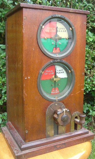
LNER instruments are particularly interesting, since they show a variety of block controls, and - with the help of the Standard Wiring Diagrams - it is possible to trace the devlopment of the circuits. I make no claim that these notes are exhaustive - indeed it is not my intention that they should be. At the moment only 3 wire 3 position instruments are described. There is no mention, for example, of the early 1-wire instruments, which were used on the ex-GER and ex-WMCQR. Overview of 3 wire, 3 position block 3 wire, 3 position block is so called, because there are 3 wires, one for each line (up and down), and one for the bell, with earth return. The 3 positions are line blocked (no current in block line), line clear and train on line (current flowing in opposite directions). Most of the early block instruments had a commutator which allowed a single cell to be disconnected from line (line blocked) or connected - either way round - between line and earth, like this: The terminals are lettered as shown in many instruments.
The early block instruments had no connection with the signals or
track circuits, and so acted purely as a reminder of the state of the section, according to the last exchange of bell
signals. This I refer to as simple block (sometimes called free block).
With time, block controls were introduced, which linked the block instrument to the signals or track circuits, and
provided greater protection against human error. On the LNER (and also LMS) the simplest block controls generally
had
two components:
Home Normal Control (also called signal proving): the home signal must be put back to danger, before you can peg line clear for the next
train. This gaurds against forgetting to replace home signal, and ensures there is always signal at danger
between trains.
Track Circuit Control of needle: this requires a track circuit in rear of the home signal, and occupation of this
track circuit forces the needle to train on line, regardless of the position of the commutator. This gaurds against
a train waiting at the home signal being forgotten about.
(It is also worth noting that the section signal is often released by line clear from the signal box
in advance, but this does not affect the circuits for the pegging instrument, so will not be discussed further here.)
Some early examples of home normal control I have listed under early circuits.
Late in its existence, the Great Northern Railway introduced a combined block instrument which had a mechanical
pointer instead of the needle indicator for the pegging part of the instrument (the best known
examples were probably those at Spalding No 1). Block controls on these necessarily
had to be applied a rather different way - these are described under
ex-GNR mechanical block.
Following a major accident at Welwyn Garden City in 1935, caused by a signalman accidently admitting a second
train into a section, the LNER introduced another layer of block control. This is usually called Welwyn control, and works
as follows: once line clear sent to line, it is impossible to send another line clear, until a track circuit at
the home signal has been occupied and cleared. Put another way, once a train has been signalled, it must
actually run and
prove it has left the route, before we signal another train behind it.
The earliest circuit I've seen showing Welwyn control is dated 1940, and is one of the LNER's 'Standard
Wiring Diagrams'. It allows for the three types of block control to be
added in a modular fashion (so the home normal or signal proving only version is effectively the same
as some of the early circuits).
I call this circuit 1A. This later evolved into
circuit 1B.
So far, all the circuits described have been built around the same commutator - this one:
The extra contacts required for the block controls were obtained by
mechanically modifying the block instrument, or by using an 'extended' commutator with additional contacts
built in.
In a diagram dated 1945, we find something quite different - a rotary commutator, made by Tyer and Co:
The terminals are lettered as shown in many instruments.
The early block instruments had no connection with the signals or
track circuits, and so acted purely as a reminder of the state of the section, according to the last exchange of bell
signals. This I refer to as simple block (sometimes called free block).
With time, block controls were introduced, which linked the block instrument to the signals or track circuits, and
provided greater protection against human error. On the LNER (and also LMS) the simplest block controls generally
had
two components:
Home Normal Control (also called signal proving): the home signal must be put back to danger, before you can peg line clear for the next
train. This gaurds against forgetting to replace home signal, and ensures there is always signal at danger
between trains.
Track Circuit Control of needle: this requires a track circuit in rear of the home signal, and occupation of this
track circuit forces the needle to train on line, regardless of the position of the commutator. This gaurds against
a train waiting at the home signal being forgotten about.
(It is also worth noting that the section signal is often released by line clear from the signal box
in advance, but this does not affect the circuits for the pegging instrument, so will not be discussed further here.)
Some early examples of home normal control I have listed under early circuits.
Late in its existence, the Great Northern Railway introduced a combined block instrument which had a mechanical
pointer instead of the needle indicator for the pegging part of the instrument (the best known
examples were probably those at Spalding No 1). Block controls on these necessarily
had to be applied a rather different way - these are described under
ex-GNR mechanical block.
Following a major accident at Welwyn Garden City in 1935, caused by a signalman accidently admitting a second
train into a section, the LNER introduced another layer of block control. This is usually called Welwyn control, and works
as follows: once line clear sent to line, it is impossible to send another line clear, until a track circuit at
the home signal has been occupied and cleared. Put another way, once a train has been signalled, it must
actually run and
prove it has left the route, before we signal another train behind it.
The earliest circuit I've seen showing Welwyn control is dated 1940, and is one of the LNER's 'Standard
Wiring Diagrams'. It allows for the three types of block control to be
added in a modular fashion (so the home normal or signal proving only version is effectively the same
as some of the early circuits).
I call this circuit 1A. This later evolved into
circuit 1B.
So far, all the circuits described have been built around the same commutator - this one:
The extra contacts required for the block controls were obtained by
mechanically modifying the block instrument, or by using an 'extended' commutator with additional contacts
built in.
In a diagram dated 1945, we find something quite different - a rotary commutator, made by Tyer and Co:
 One of three pairs of contacts are closed at each of the three commutator positions.
The terminals are numbered in the instrument as shown. You may wonder why this
commutator is constructed like it is - I suspect there may be a story behind it, but that
is for the future!
Circuits using this
commutator I refer to as
circuit 2.
One of three pairs of contacts are closed at each of the three commutator positions.
The terminals are numbered in the instrument as shown. You may wonder why this
commutator is constructed like it is - I suspect there may be a story behind it, but that
is for the future!
Circuits using this
commutator I refer to as
circuit 2.